Agenda
- SSD Flash
- SDR main board installation
- PC to SDR main board connections
- ORS packaging
- Panel and ERP5 processes
This tutorial teaches how to assemble an Open Radio Station, and package it if necessary (to sell it on shop.rapid.space).
Make sure you have available licences
Check you have one "AMARI NR Small Cell" and one "AMARI 4G 5G CORE D" before assembling the ORS.
Flash the SSD
- Take an empty SSD, insert the SSD in the USB to M2 SATA adaptor and then plug the USB to your computer.
- Run the flash_image command:
- Input your gitlab username and password when asked
Take out the enclosure and waterproof RJ45 connector

Warning: Please do not plug or unplug the POE RJ45 cable from the ORS while injector is powered on.
- To unplug ORS: Unplug the electrical cord between the POE injector and the electrical outlet, then the RJ45 POE
- To plug ORS: plug RJ45 POE to the ORS, then plug POE injector to electrical outlet
Doing otherwise might break some electrical components inside the ORS. Even if the ORS has been manually powered off through SSH (for those having root access) you still need to follow this procedure to unplug it.
Prepare Waterproof Cable Mount Connector

Prepare the waterproof cable mount connector from your ORS package and a shielded Ethernet cable.
Waterproof Cable Mount Connector

Split the connector to 4 parts. Note that C is inside of B.
Cut rubber ring C

Please have C cut as shown in the picture.
Note: cutting rubber ring C is in order to pass the Ethernet cable through. Instead of doing this, you can also make your Ethernet cable so the cable itself can go through the rubber without the RJ45 connector.
Pass the cable

Pass the shielded Ethernet cable through D C B A in order.
Connect parts

Connecting each part tightly as original.
Tighten the connector

Turn tight D so that there is no gap between shielded Ethernet cable and rubber ring C.
Open the enclosure

Use a hexagonal screwdriver to remove the 8 screws from the enclosure.
Apply thermal interfaces (New enclosures)
If you have a new enclosure (Enclosure V4) compatible with the new 2 x 1W PCBs, apply thermal paste and thermal sheet this way:

Apply thermal interfaces (Old enclosures)
If you have an old enclosure (Enclosure V3) compatible with the 2 x 0.5W PCBs, apply thermal paste and thermal sheet this way:

Install the SDR main board
Warning: Make sure PCB and enclosure match, new PCB v4 will break if put inside an old enclosure !

Install the SDR main board with M2.5 screws * 17. Start by very lightly screwing all screws, then once all screws are placed tighten them all. Write down the PCB board number.
Prepare the electrical wires

Take out the LED wires and close the ORS lid while cutting excess metal wire, as small metal bits landing on PCB could break it. Cut a red and black wire of 23cm for the PC supply, and strip and tin around 4mm at each side.
Connect the wires to PTSM connectors


Connect the LED wires and the PC supply cables in a PTSM connector. The metal wires should not stick out of the PTSM, cut them if necessary. Use a SIM pin to open the PTSM connector in order to insert the cable into it as shown on the image.
Twist the power supply wires
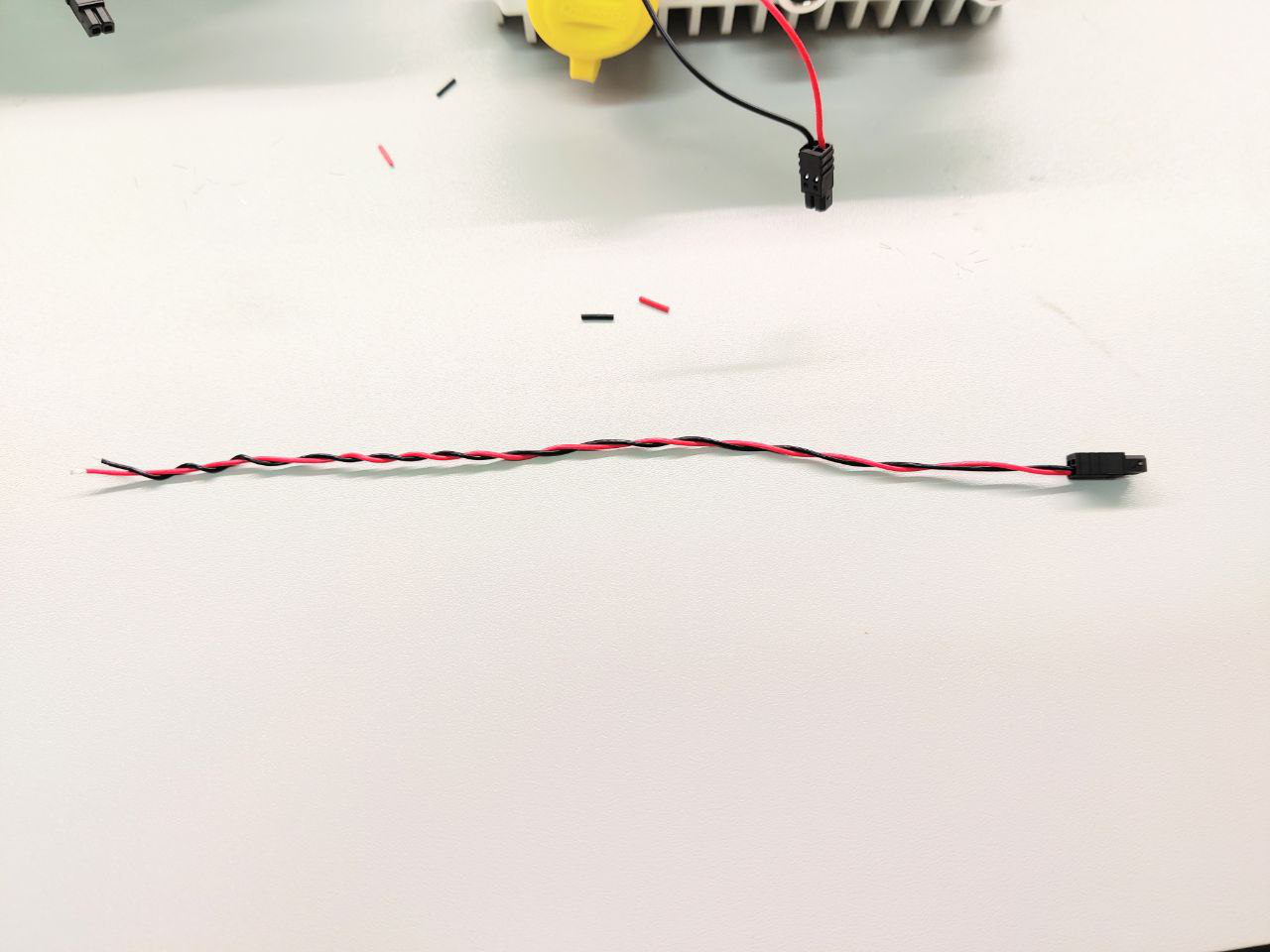
Twist the power supply wires
Connect the LED wires and RJ45 cable


Plug the PTSM connector from the LED wires in the SDR main board. Plug an armored RJ45 cable between the ORS power input and the PCB power input. If the RJ45 cable is too long, use an insulated cord to hold it in place.
Remove the plastic films

Please remove the plastic films before you plug the coax cables.
Twist the RF coaxial cables (old enclosure)
This is how to install RF coaxial cables on old enclosures. (procedure needs to be updated for new V4 enclosures)
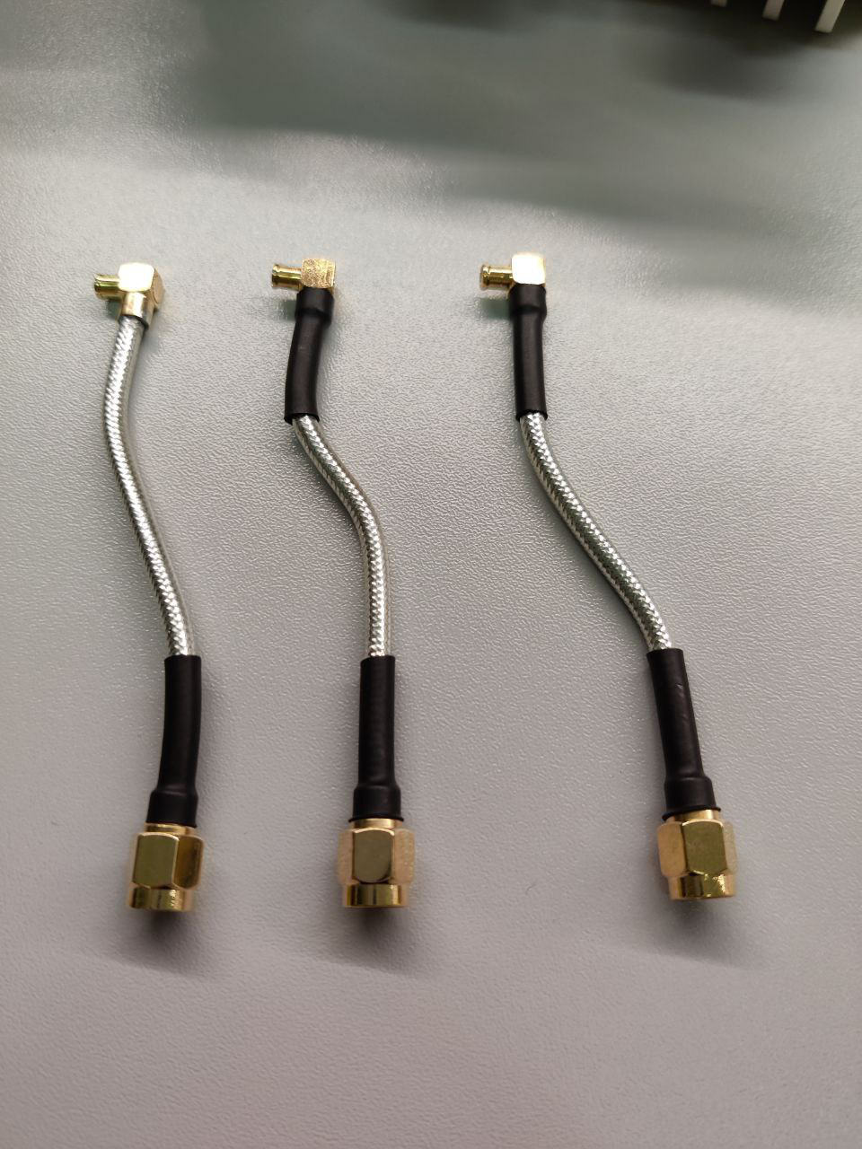
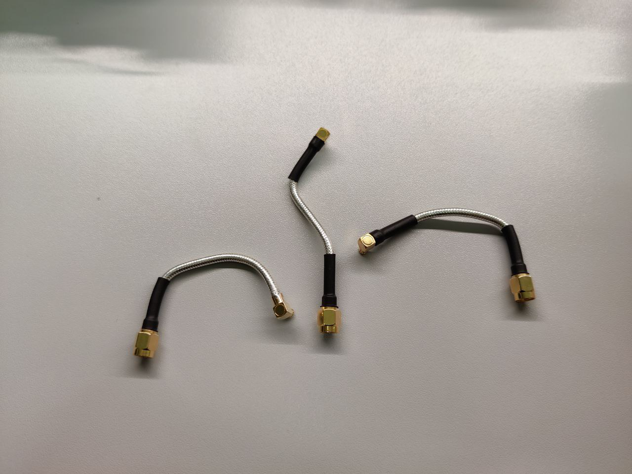
Twist the 3 RF coaxial cables by first twisting them in the vertical plane, then the horizontal plane. Don't use pliers or tools that could break the cables, they are fragile.
Plug the RF coax cables (old enclosure)
This is how to install RF coaxial cables on old enclosures. (procedure needs to be updated for new V4 enclosures)

Plug the 3 RF coax cables. Remove the black cable sleeve on the Radio 2 as shown on the image. First put Radio 2 cable, then Radio 1, then GPS. The connector on the boards are fragile, please be careful.
Paste SBC(PC) on the enclosure


On the other part of the enclosure, install the Single Board Computer with the M3 screws. Please remove the plastic from the bottom of SBC before you paste. Fix it with 4 screws (14cm)
Install PC

Install the DDR4 SODIMM, the MSATA SSD and the PCI Express adaptor board.
Set the jumpers on the SBC

Set the jumpers on the SBC.
Connect power cable to the SBC


Please put the enclosure with SBC and the other side on the same plane like the figure shown. Connect the power cable to the SBC.
Connect the power cable between PTSM and SDR
Warning: If the power cable is plugged in the wrong order or to the wrong port you will break the PCB !

Connect the power cable in a PTSM connector and plug this connector in the SDR main board.
Connect ribbon FFC

Connect the ribbon FFC between the PCI Express adaptor board and the SDR main board.
Connect the second RJ45 cable

Connect the second RJ45 cable between the SBC and the SDR main board.
Checklist before closing the ORS
Before closing the ORS, please be 100% sure all this is correct:
- Power cable is plugged to the "PWR_PC" port on PCB and red and black wires are in the right order as shown on photo (very important)
- Both yellow jumpers are correctly placed
- SSD was flashed correctly
- The red waterproof seal is placed correctly
Close the ORS

Before closing the ORS, you can blow some compressed air on the PCB to make sure there are no metal dust on it. Also write down the PC serial number. Close the enclosure and connect the PoE cable to start the system.
Place Labels on the ORS


Place a "ORSXX" label on the interior of the case of the PC, and on the exterior of the case as shown on the images
Power on the ORS
Power on the ORS.

Clone the ors-util repository:
root@orsXX:~# git clone https://lab.nexedi.com/nexedi/ors-utils.git

root@orsXX:~# cd ors-utils/uicc

root@orsXX:~# make
Execute this command:
root@orsXX:~# ./write-sim-card ORS_NUMBER
Once the first SIM card is plugged, press the Enter key
Wait until all the transfer is done, then put the next sim card, and press Enter key again. Do this for all 5 SIM cards.
Test the SIM cards and ORS
Test that each SIM card can connect to the ORS by putting it in a UE. Please also test the UE can connect to the ORS from a distance with a good enough bandwidth, to make sure the connection between SDR board and ORS box is fine.
Poweroff the ORS
Make sure all services are green before powering off the ORS.
Place warning labels on the POE connectors


Please put labels saying "Do not hot plug/unplug" on the POE connectors before packaging the ORS.
Put the ORS back in the enclosure box

Write down the enclosure serial number. Then put the ORS back in the enclosure box.
Arrange the Antennas, N to SMA adaptors, and ORS mount kit in the box as shown on the image.
Prepare the ORS package with accessories
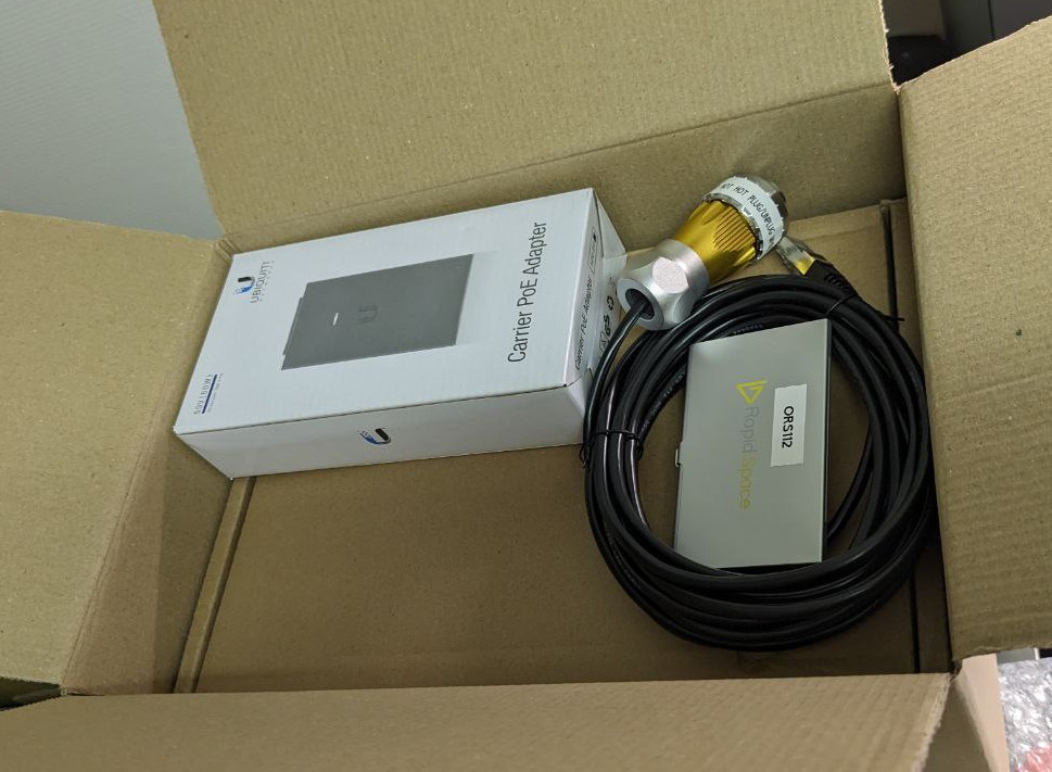
Arrange the ORS box, RJ45 POE cable, and sim cards in the box as shown on the image.
Box dimensions: 310x220x200 mm , 3.5 kg
Checklist before closing the package
Before closing the package, please be 100% sure all this is correct:
Before filling the package with package fillers, please be 100% sure you did all this correctly:
- Test all SIM cards
- Write down all serial numbers and information related to ORS (PCB, PC, Box, MAC address, password)
- Have all screws tightly screwed on the enclosure
- Have in the package:
- the ORS Box
- the power injector
- The RJ45 POE cable with its connector
- The Antennas
- The N-to-SMA adaptors
- The SIM cards
- If the ORS is to be sent outside of Europe, print the invoices for customs and put in the package before closing it
- Print the sale packing list and include in the package
Close the package
Close the package once you have gone through the checklist

Send the welcome mail
Run the script to generate the welcome mail.
For root access:
laptop:~/WORKDIR/slapos-deivce-configuration/cli# ./generate_ors_email.py -r -m MAC_ADDRESS -i PUBLIC_IPV6 -l {200,600} {dhl,la_poste,in_person} tracking_number login email product_list
Else if client hasn't bought root access:
laptop:~/WORKDIR/slapos-deivce-configuration/cli# ./generate_ors_email.py {dhl,la_poste,in_person} tracking_number login email product_list
Then copy paste the html code in your email client in HTML source code mode.